
Cubic‑S Basic Setup E01 Controller
What Cubic‑S Is
Cubic‑S is Kawasaki's hardware safety option for the E-series controller. It is a dual-channel, self-monitoring board that watches the robot's actual motion, joint angles, speed, tool position, and three-dimensional zones, independently of the main robot CPU, and cuts motor power when the robot violates a configured limit.
It provides safety-rated functions including motion-area monitoring, constant/selectable monitoring zones, joint-range monitoring, speed monitoring, tool-orientation monitoring, protective stop, and emergency stop, with dual-channel safety inputs and outputs. The board is configured from a PC using the CS-Configurator software over USB-B, and its safety state is tied back to the robot's AS software through a CRC "safety signature."
Cubic-S commissioning is safety-critical work. Setup, parameter entry, and validation must be performed by personnel trained/certified on Kawasaki safety systems. This page is an orientation checklist, not a substitute for the Cubic-S, Safety, Operation, External I/O, and Installation & Connection manuals - keep them open alongside this procedure.
Before You Begin
Confirm the following before touching software or wiring:
- The Cubic-S unit is physically installed in the controller (board, 1XL relay board, harnesses, and override switch on the accessory panel for E0x).
- You have the CUBICS_ON.as file (supplied with the Cubic-S option) on a USB flash drive.
- A PC with CS-Configurator installed and the USB driver working, plus a USB-B cable.
- The robot is at a known, safe pose and the cell is clear. All wiring is done with controller power OFF.
Enabling Cubic-S and the power cycles that follow can trigger an encoder-value comparison error and, in some cases, disturb zeroing data. Record your encoder/zeroing data before enabling anything so you can restore it cleanly.
Record the Current Encoder Values
Cubic-S stores its own copy of the encoder values and compares them across power cycles. The first power-up after enabling Cubic-S (or after replacing it) can raise E9419 — Encoder value error, which forces a zeroing check. Capture a complete record now so restoration is trivial.
A. Save a full backup (recommended)
From the teach pendant, save Robot Data (*.rb) to USB — this file includes zeroing data along with dedicated-signal settings. Use the Aux Save function (Save → Robot Data). Keep this file; it is your one-step restore.
B. Manually note the zeroing values
As a record, write down the per-joint zeroing and offset values:
# Teach pendant
AUX 050105.01 → 05010205.01.02  Zeroing Data Set / Display
   ⤷ note JT1–JT6 zeroing values
   ⤷ <Next Page> → note OFFSET values (do not change them)
C. Snapshot the live encoder readings
For reference, the raw values are visible under the monitor screens:
- Monitor 10.5 — Joint encoder value (current encoder counts per axis)
- Monitor 10.15 — Encoder original data
AUX is a maintenance function — viewing is safe, but changing values alters the robot's detected position and its taught trajectory. Only enter values during a deliberate restore.05010205.01.02
Load the CUBICS_ON.as File
The CUBICS_ON.as file switches on the Cubic-S software option inside the controller (it sets the system data/switches that tell AS the option is present). Load it from the USB drive into robot memory.
Load from USB
# Monitor terminal (or TP keyboard screen)
> USB_LOAD CUBICS_ON     # ".as" extension is added automatically
Alternatively, use the pendant Aux Load function and select the file from the USB drive. If a /Q-style prompt appears (Load? 1:Yes 0:No 2:Load all 3:Exit), choose 2 (Load all) to take the full file.
- Insert the USB drive containing
CUBICS_ON.as. RunNavigateUSB_LOADtoCUBICS_ON(or02.02- Select
→Cubics_ON.asLoadso→thatfromitUSB).appears in the File Name header - Press the LOAD button.
- Confirm Yes.
- When prompted "Are you sure?", input 1 and press enter
- Cycle controller power (OFF → ON) so the option enable takes effect.
Changes that affect the Cubic-S option/parameters are only reflected after an OFF/ON of control power. Expect Cubic-S errors such as E9404 — Parameter may be changed. Turn OFF & ON the control power for verify until you power-cycle. This is normal during commissioning.
Jumpers & Connectors / Enable Internal Power
All steps in this section are performed with controller power OFF and the main disconnect locked out.
A. Set the 1TR board jumpers
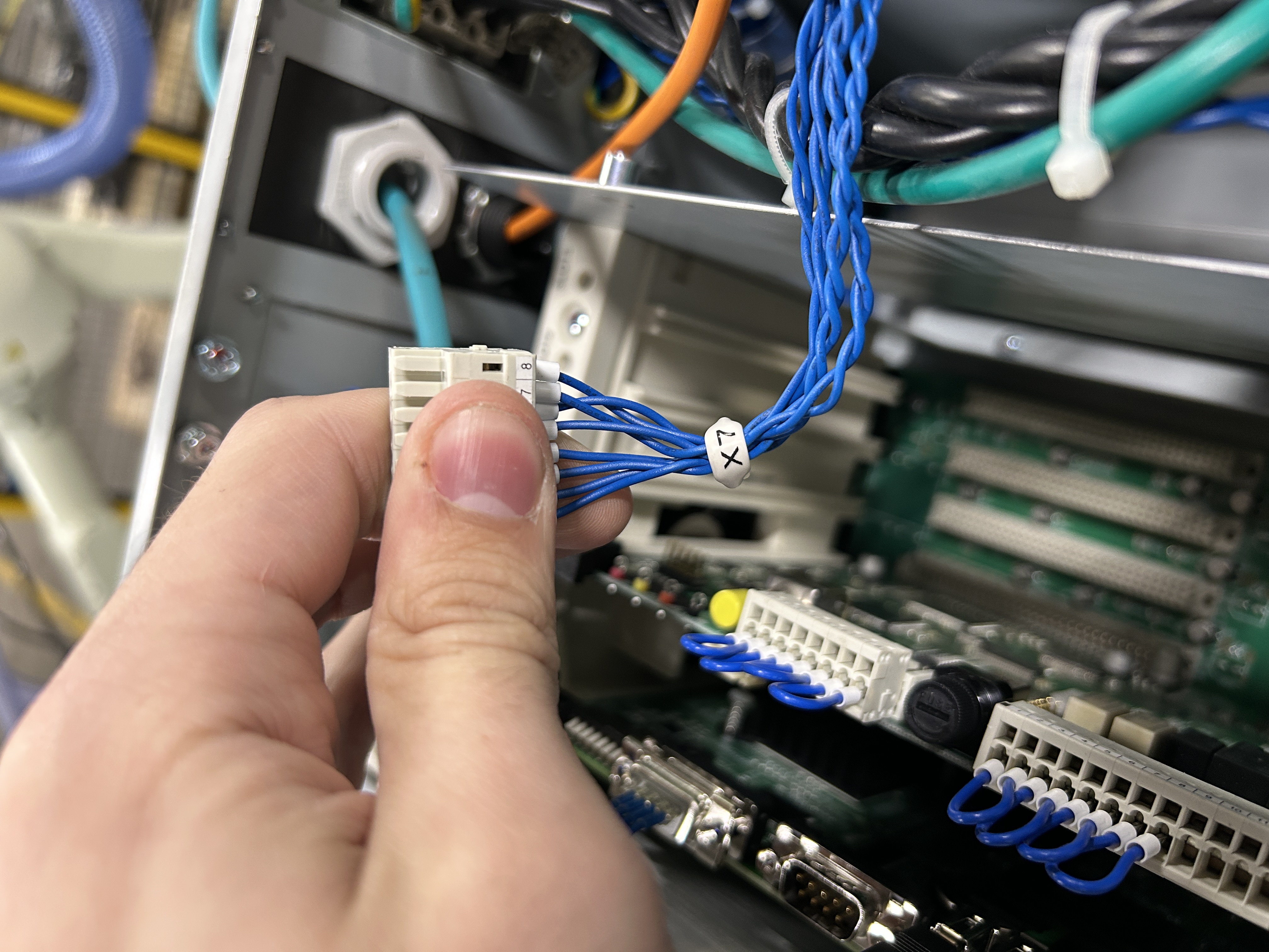
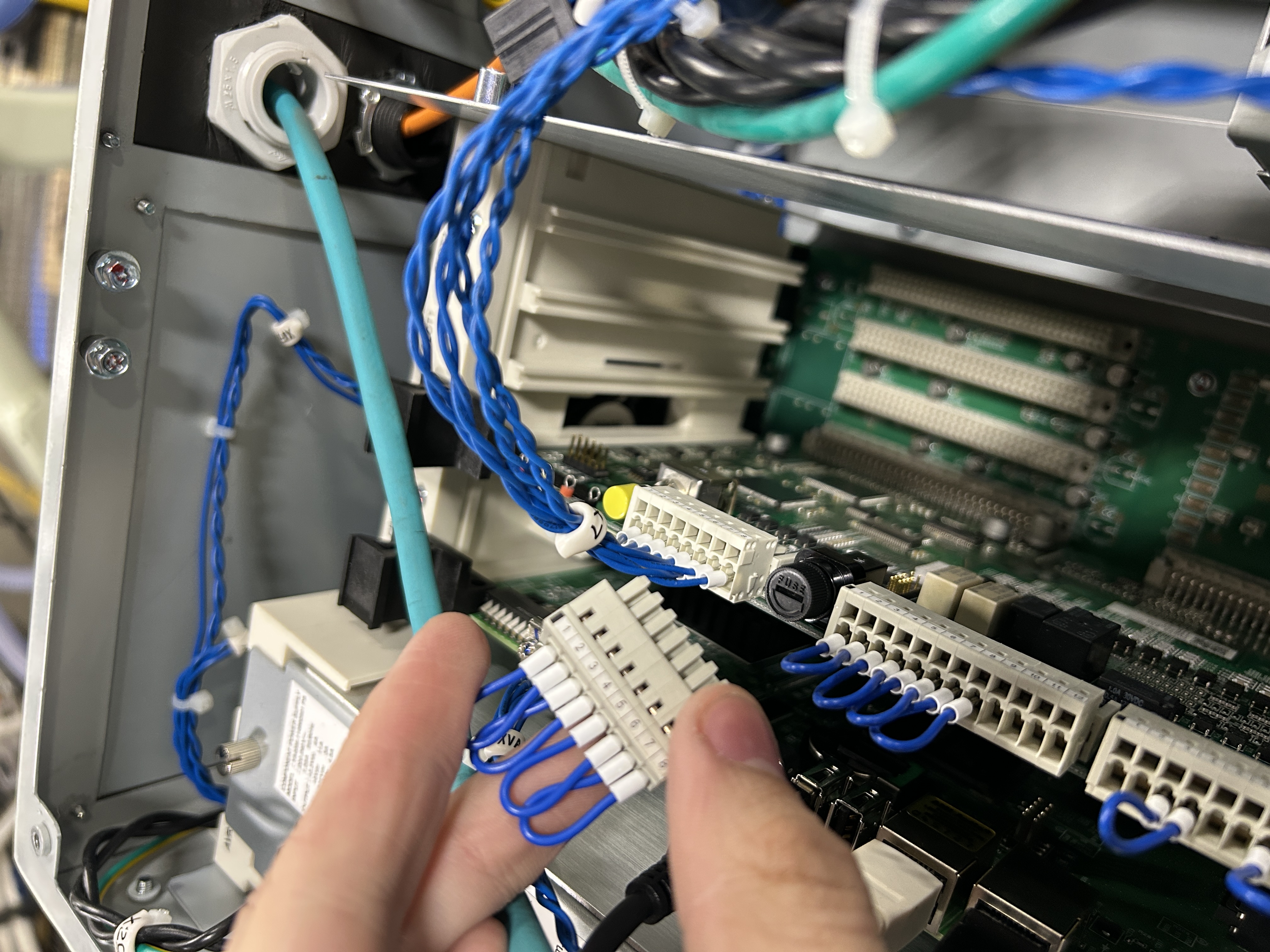
X7
OnIf the controller is straight out of the box, there should be a Cubic-S–equippedjumper controller the safety circuit is fixed to two systems. Move the JP1 / JP2 jumpersconnector on the 1TRmotherboard. boardThis jumper needs to thebe JP2replaced side.with Ifconnector leftX7. onSave the wrong side, Cubic-S will detect an errorjumper and willdon't notlose enable.it.
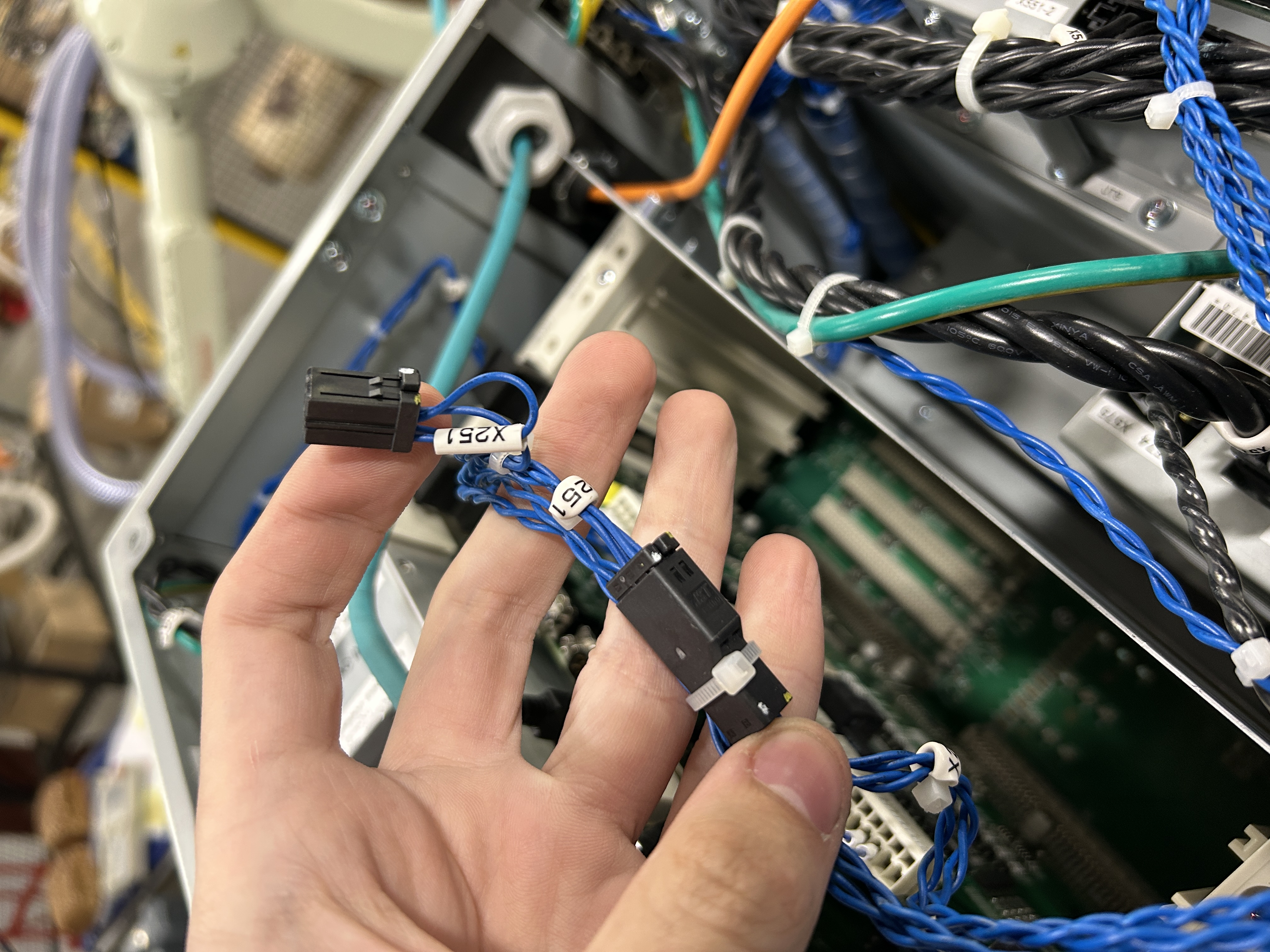
X251
X251 (requiredis the feedback for Cubic-S).the
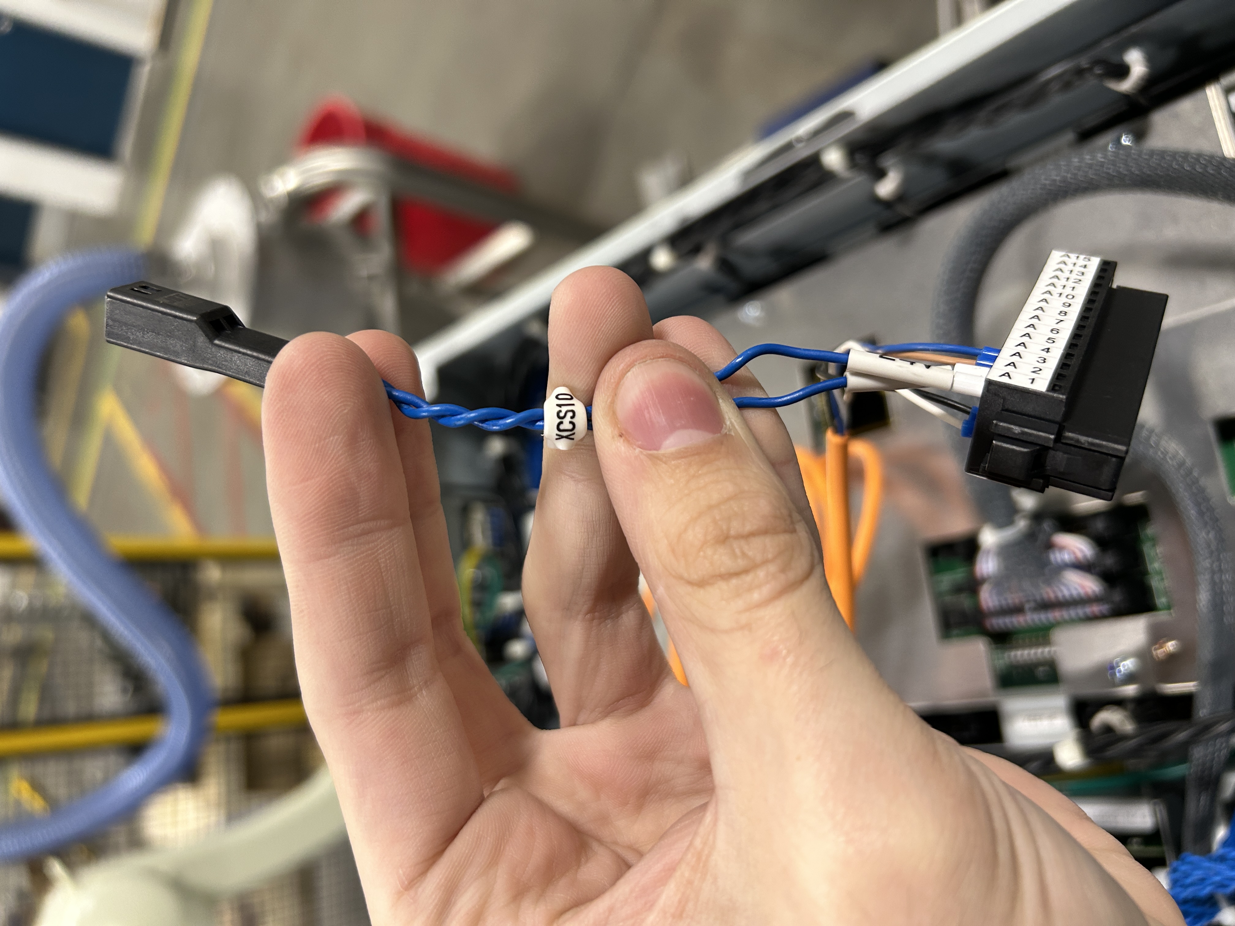
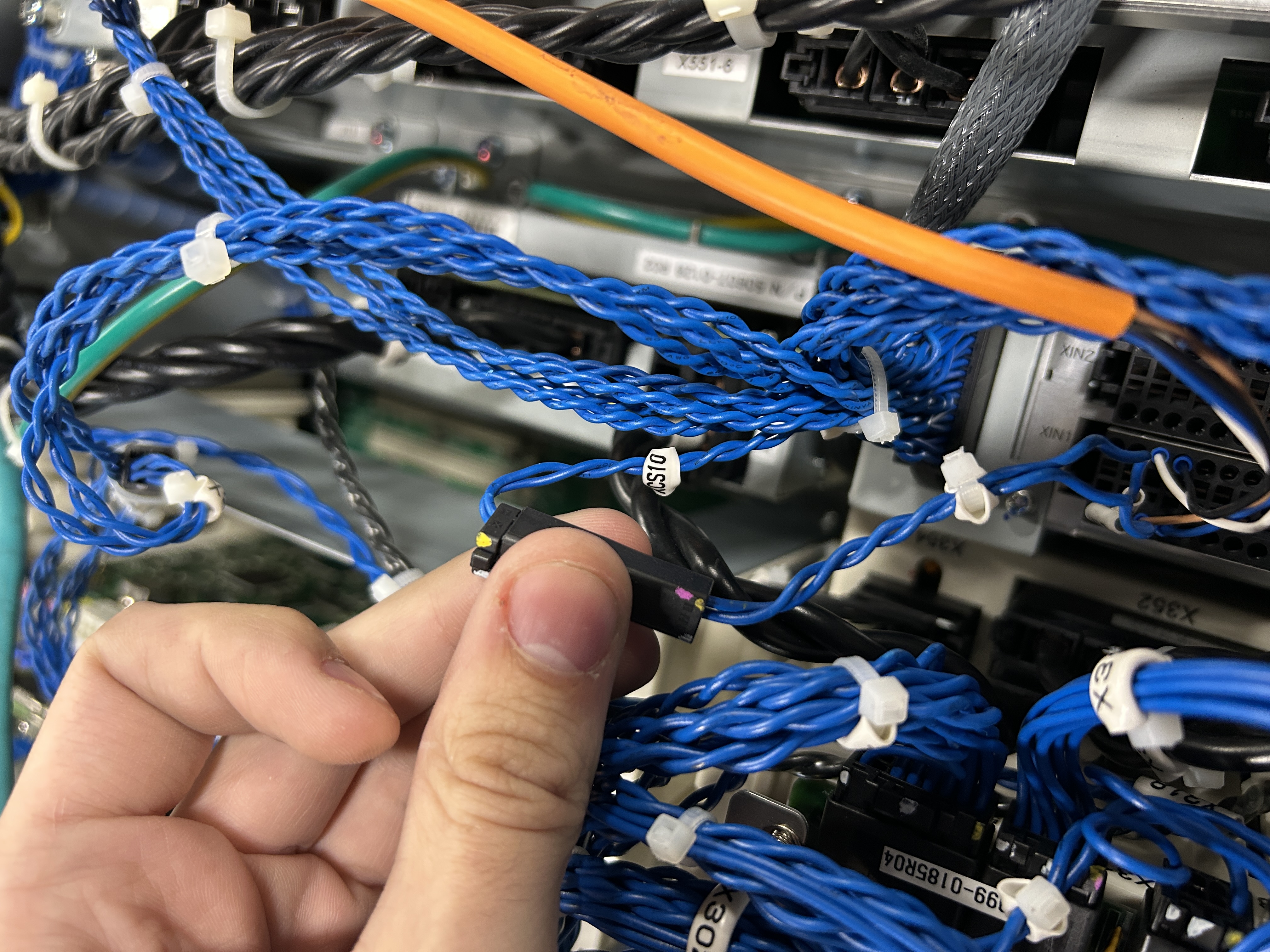
B. Route internal 24 V to the safety input card (XCS10)
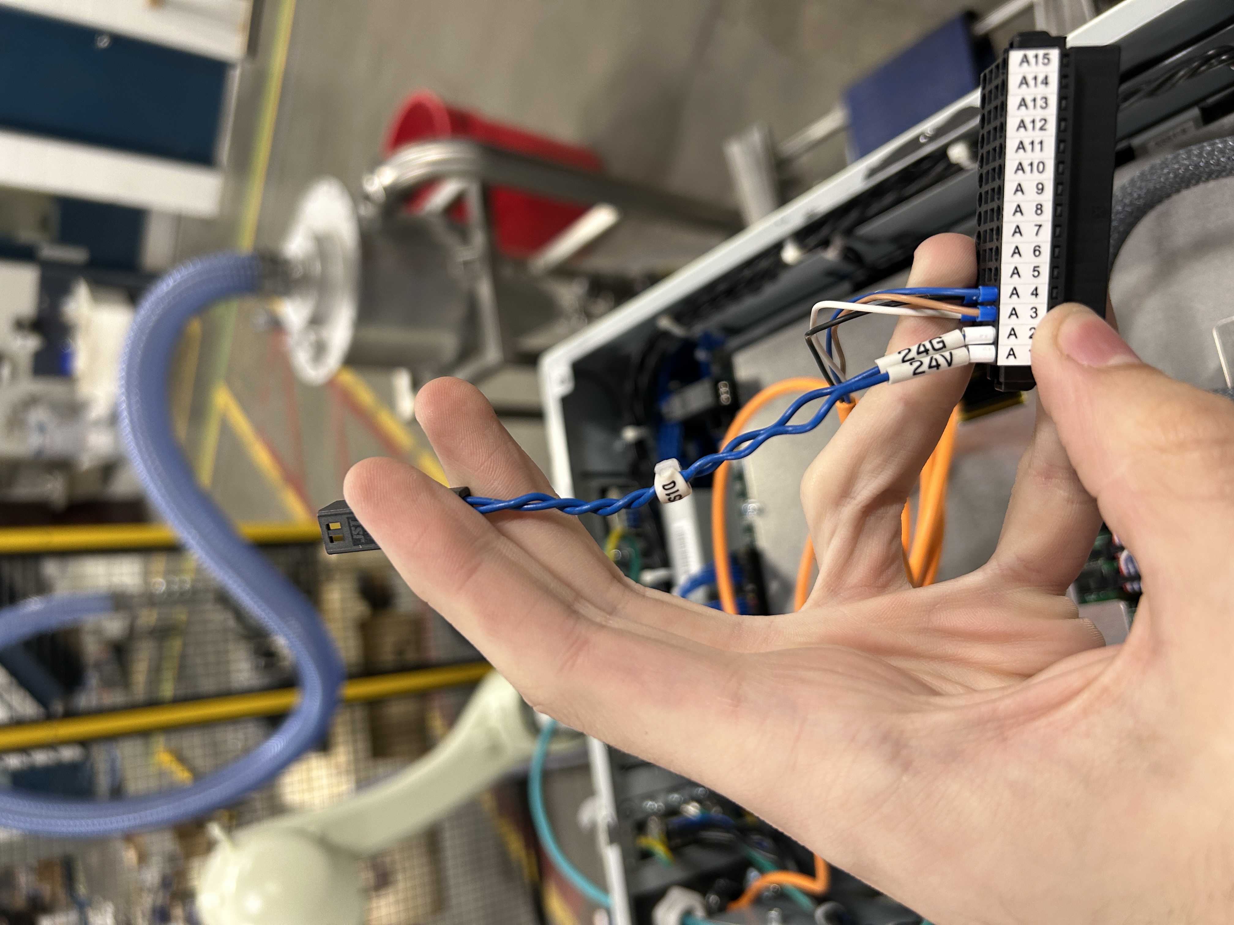
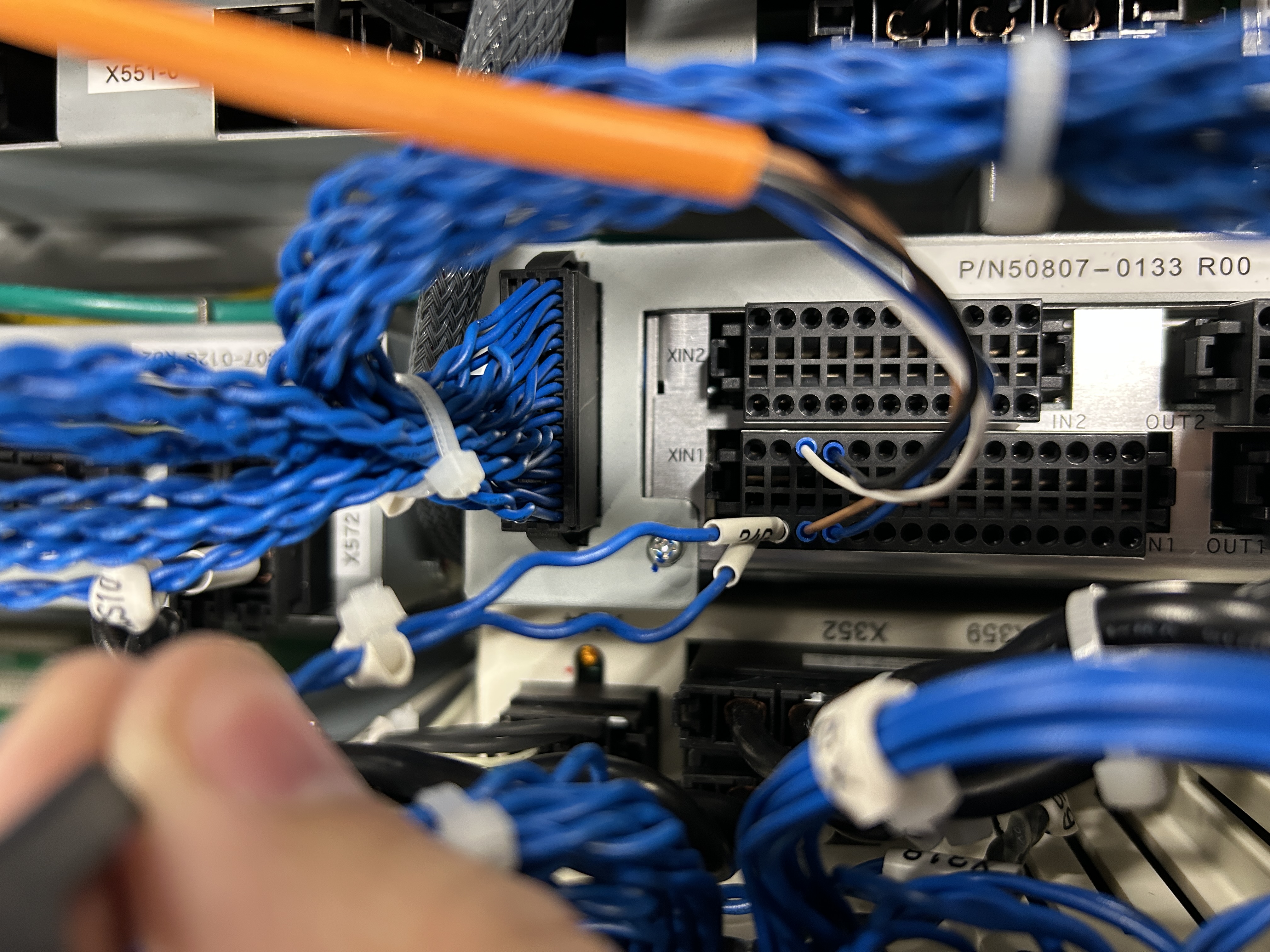
The Cubic-S user safety I/O needs 24 V. Where no external supply is available, the controller's internal 24 V is brought in through the XCS10 harness (shipped attached to the controller but unconnected by default). The harness's connector head mates to the XCS10 internal-power port on the relay (1XL) board side; its conductors feed the XIN1 power terminals.
| XIN1 pin | Signal | Source |
|---|---|---|
| A1 / B1 | +24 V (V13) — XIN1 power supply | XCS10 +24 V (internal) |
| A2 / B2 | 0 V (G13) — XIN1 GND | XCS10 0 V (internal) |
When powering the safety I/O via the XCS10 harness, the total load on the user safety input/output must be 0.5 A or less. A dry e-stop contact is well within this.
Reference the E0x default wiring diagram (Cubic-S manual, 9.3, page 9-13) to confirm X7 / X251 / XCS1 / XCS2 routing for your controller before energizing.
Wire an E-Stop to Safety Input 1
User safety input Ch1 lives on the XIN1 connector. It is a dual-channel, self-testing input: the board emits test pulses (TP-A / TP-B) that must return through the e-stop switch contacts into the input pins (IN1-A / IN1-B). A dry two-contact e-stop switch is all that is required, four signal conductors, with 24 V supplied internally via XCS10.
| Pin | Name | Function |
|---|---|---|
| A3 | IN1-A | Safety input Ch1-A |
| B3 | TP-A | Test pulse output A → through e-stop contact 1 → A3 |
| A4 | IN1-B | Safety input Ch1-B |
| B4 | TP-B | Test pulse output B → through e-stop contact 2 → A4 |
Wire each e-stop contact in series between its test-pulse output and the matching input pin, so an open contact removes the pulse and trips the channel.
Connector / wiring notes
- The XIN1 safety-I/O receptacle is a screwless spring-clamp connector — do not cut connector heads off harnesses to land them here.
- Conductors: AWG24–AWG20, strip length ~7.0 mm, or use ferrule terminals.
- Use shielded cable, routed away from power/high-voltage lines.
After any change to emergency-stop wiring, confirm without fail that every e-stop button actually stops the robot before relying on the circuit.
Basic Settings in CS-Configurator
With wiring complete and the controller powered, connect the PC and configure the safety parameters. On the E0x the Cubic-S USB port is inside the accessory panel, next to the override switch.
- Connect. Plug the USB cable PC ↔ Cubic-S. In CS-Configurator open the Operation Menu tab and press <Read Robot Parameters>. The status icon switches to "connected" and the robot parameters (grey rows) load.
- Allocate the e-stop function. In the Parameter Tree View, open the safety-input settings and allocate the Emergency Stop function to User Safety Input 1 (the Ch1 you wired in).
- Set the dual-input logic for that channel:
- Logic:
Equivalent(both contacts close together) orComplementary— match your switch type. - Allowed time of discrepancy:
0–30000 msmismatch window before a channel-disagreement fault (a few hundred ms is typical for a mechanical switch).
- Logic:
- Configure your monitoring functions (motion area, joint range, speed, etc.) as the cell requires. For a first power-on you may keep these minimal and expand later.
- Write. Press <Write Parameters to Cubic-S>. A password is required — the v2 factory default is
khi. (In v1 the password is set on first write and stored on the PC.) - Verify. Press <Verify Cubic-S Parameters>; mismatches show red in the data view. Resolve any before proceeding.
- Power-cycle the controller so the written parameters are reflected and validated by Cubic-S.
Robot parameters (grey) come from the controller via <Read Robot Parameters> and cannot be edited. User parameters (white) are what you set per monitoring function. Both are pushed by <Write Parameters to Cubic-S>.
Register the Cubic-S Safety Signature
Cubic-S protects its configuration with a CRC "safety signature." AS keeps a stored copy; after you finalize parameters you must register the current CRC so the controller and Cubic-S agree — otherwise you'll get repeated signature/parameter-change faults.
# Teach pendant
AUX 0820  Cubic-S Safety Signature
   ⤷ displays current Cubic-S CRC vs. CRC stored in AS
   ⤷ press <Confirm> to rewrite AS with the current Cubic-S value
Run this after the final <Write Parameters to Cubic-S> and power cycle. Re-run it any time you change Cubic-S parameters. (If the dedicated input "Cubic-S Safety Signature Reset" is active, <Confirm> is hidden by design.)
Restore Encoder Values If Wiped
If enabling Cubic-S disturbed the zeroing data, or the first post-enable power-up raised E9419 — Encoder value error (check zeroing / home pose), restore the values you captured in §02.
- Switch to TEACH mode and reset the error. (E9419 is reset-acceptable in teach mode.)
- Check the pose. Verify the zeroing pose and home pose. With axes on their scribe marks, every joint should read 0°.
- Restore the data by whichever record you took:
- Fast path — Aux Load → Robot Data (*.rb) from your §02 backup (restores zeroing data in one shot).
- Manual path — re-enter the per-joint values in
AUX 050102Zeroing Data Set/Display, then confirm until "Setting complete." appears.
- Re-confirm the zeroing/home pose is correct before leaving teach mode.
Do not resume automatic operation on a robot whose zeroing you have not verified. A wrong current value means the robot pose can deviate from the program. If a motor/encoder was actually replaced, perform full zeroing and reset the rotation counter (AUX 050103) — not just a value re-entry.
A single E9419 right after first enabling Cubic-S (or right after a power cycle that immediately follows turning zeroing on) is listed as a non-abnormal case — but you must still confirm the pose before clearing it.
Final Confirmation
Before handing the cell over, validate end to end:
- E-stop function: pressing the wired e-stop removes motor power; releasing + reset restores it. Test both channels behave together within the discrepancy window.
- Safety I/O: confirm input/output states on the TP safety-signal monitors and the XIN1 IN1 power LED is ON.
- Monitoring functions: jog into each configured limit and confirm Cubic-S trips as expected.
- Signature: confirm no outstanding parameter-change/signature faults remain.
Record the final Robot Data (*.rb) backup, the CS-Configurator parameter file, and the registered safety signature in the project file for this E01