
Hygienic Design Principles for Conveyors
Guide to Hygienic Conveyor Design
A short YouTube series by Commercial Food Sanitation LLC (CFS) outlining hygienic conveyor design principles can be found here: https://www.commercialfoodsanitation.com/news/cfs-short-course-3-introduction-to-hygienic-conveyor-design
Equipment Design Guidelines / Standards
- AMI Principles - Wet Environments
- GMI - Low Moisture Environments
- 3A Standards
- ISO 14159
- EN 1672
- ANSI Z50.2
- AWS - American Welding Standards
- NSF/ANSI/3-A SSI 14159-1-2014
AMI Principles for Wet Environments
The following 10 principles of sanitary design are recommended by the AMI for Sanitary Equipment Design. They have been a leading factor in safety advances in meat and poultry plants, including the reduction of Listeria monocytogenes in ready-to-eat meat and poultry products. The most relevant points for conveyor design are bolded.
- Cleanable to a microbiological level
- Made of compatible materials
- Accessible for inspection, maintenance, cleaning and sanitation
- No product or liquid collection
- Hollow areas should be hermetically sealed
- No niches
- Sanitary operational performance
- Hygienic design of maintenance enclosures
- Hygienic compatibility with other plant systems
- Validated cleaning and sanitizing protocols
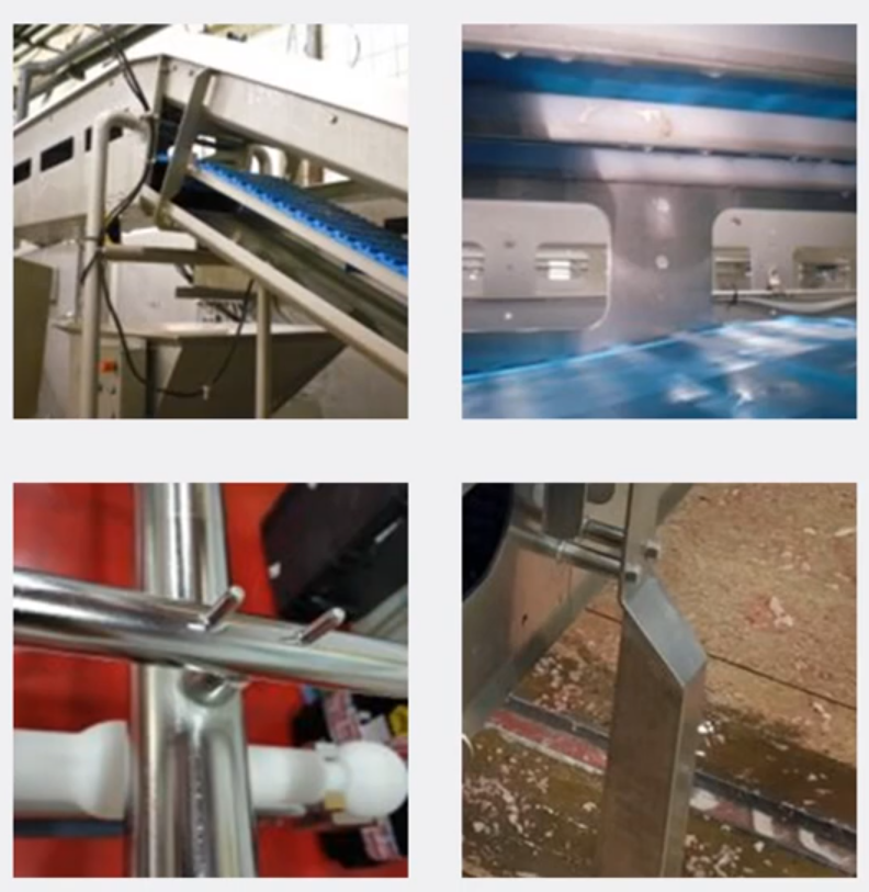
Frame & Legs
- No universal design exists.
- If hollow profiles cannot be avoided, they must be hermetically sealed.
- Sanitary welds and smooth connections are required. Minimizing joints is crucial.
- To avoid niches between connections, spacers can be used. This creates good access for cleaning.
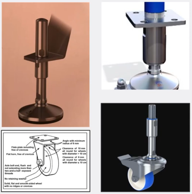
Feet & Wheels
- The connection between feet and legs should be hermetically sealed by O-rings and/or sanitary welds.
- A good rule of thumb is to have up to 10 cm (4 inches) of adjustment for feet.
- Feet should not have exposed threads.
- Avoid using materials with poor durability.
- It is preferred not to fasten feet to the floor. In cases where feet must be fastened to the floor, use hygienic designed bolts. The holes and other seams should be hermetically sealed.
- Mounting places should be self-draining, preventing from accumulating water.
- Preventative maintenance and periodic inspection should be arranged (water ingress, failed seals, etc.).
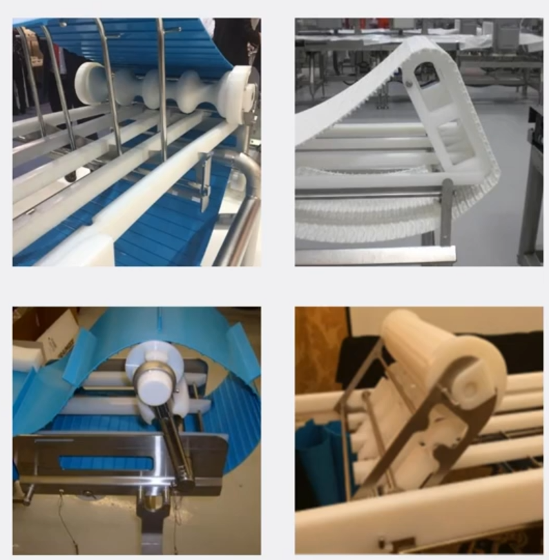
Belt Lifters
- A simple mechanism for belt or idle shaft lifting should be used to ensure all parts of the frame (and belt) can be made accessible for cleaning, disinfection, and inspection.
- A belt lifter should be designed as removable to avoid creating niches due to rotating connections.
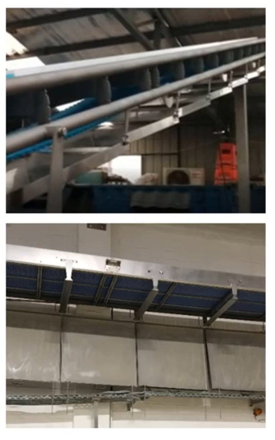
Catch Pans
- Catch pans should be designed and installed to prevent contamination of product and product contact surfaces.
- They should not be placed above or across open production areas, which may cause product contamination.
- Stainless steel is preferred, and sanitary welds and smooth connections are required.
- Catch pans should be self-draining in wet area applications.
- Easy access, or tool-less disassembly/removal for cleaning or inspection.
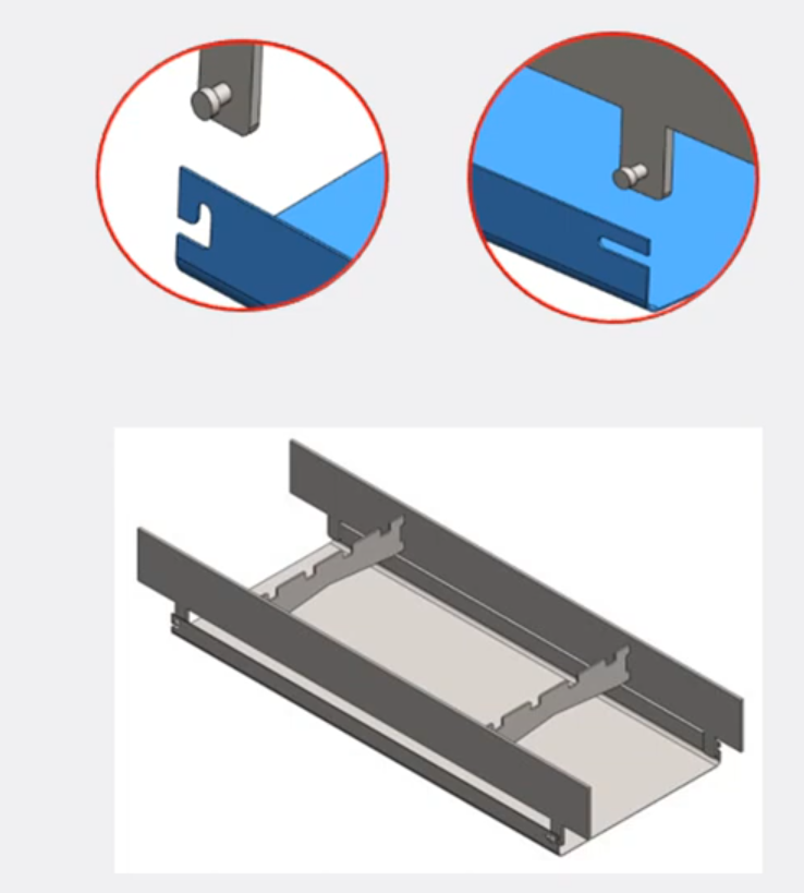
Carry way
Wear Strips
- The material of wear strips should be solid, plastic profiles with a surface finish that is smooth and does not promote microbial growth.
- Ideally, wear strips should be easily disassembled/re-assembled without tools. This allows for proper cleaning and inspection.
- Given the size, it is beneficial to have a specific cart or rack available to place wear strips on during disassembly to prevent placing them on the floor.
- Avoid lap joints and sandwiches.
- Thermal expansion and contraction may need to be taken into account.
- Best practice is to use the fewest number of wear strips. For intralox belting, the minimum number of carry way wear strips can be found in the engineering manual.
Static Shoes & Side Guards
- Like wear strips, disassembly / re-assembly should be easy and tool-less.
- Limit lap joints and sandwich areas. A spacer can be used to minimize sandwich areas (>12mm).
Return way
Dynamic Supports (Rollers)
- Press and shrink fits are not recommended for sleeved/assembled rollers since the connection between the sleeve and core roller will fill over time.
- Avoid / limit fasteners when possible.
- Return way supports are in direct contact with the belt surface, and must be considered a direct food contact
surfacesurface. - Components should be easily removed/dis-assembled for cleaning and inspection without tools.
Static Supports
- Surface structure should be smooth, without sharp edges, to prevent damaging the belt.
- Components should be easily removed/dis-assembled for cleaning and inspection without tools.
Static Supports
Motors
Types include:
- Gear motors (stainless steel or painted)
- Drum motors
- Painted motors are a viable option, but their coating / paint will fail over time.
- From the hygienic design perspective, a stainless steel motor or drum motor would be preferred.
- Motors need to be placed away from the product zone.
- Safety guards / covers for motors must be cleanable. Toolless removal is preferred where possible.
- Slotted holes on safety guarding allow for better visibility of debris.
Shaft and Sprockets
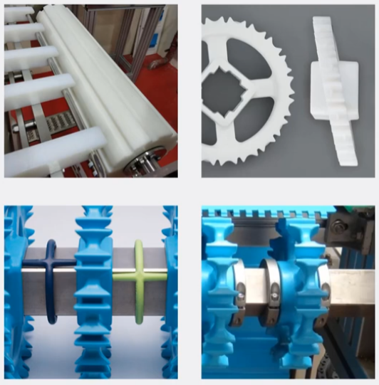
- Sprockets are often available with an easy-clean design, incorporating large windows.
- Beware of split sprockets and retaining rings as they have niches that can harbor bacteria.
- Hygienic sprocket spacers (bottom left picture below) allow for cleaning the shaft.
Position Limiters