
Ethernet IP to PLC Setup
Our goal is to set up Kawasaki communication with the PLC program such that 16 bytes of input and 16 bytes of output data are communicated between the two controllers.
Kawasaki Setup
On the robot side, all the setup can be found in Menu>Aux Function>6. Input/Output Signal
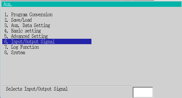
Number of I/O Signals
| Number of Output Signals | 0 |
| Number of Input Signals | 0 |
| Number of Internal Signals | 256 |
| Number of Master Signals | 128 |
| Number of Slave Signals | 0 |
16 bytes * 8 bits per byte = 128 total signals
Signal Allocation
Allocate Signals to Ports
Output (Total: 128) - MASTER 128 - SLAVE 0 - LOCAL 0
| MAS | SLA | LOC | Channel | |
| 1-16 | X | 1 | ||
| 17-32 | X | 17 | ||
| 33-48 | X | 33 | ||
| 49-64 | X | 49 | ||
| 65-80 | X | 65 | ||
| 81-96 | X | 81 | ||
| 97-112 | X | 97 | ||
| 113-128 | X | 113 |
Input (Total: 128) - MASTER 128 - SLAVE 0 - LOCAL 0
| MAS | SLA | LOC | Channel | |
| 1001-1016 | X | 1001 | ||
| 1017-1032 | X | 1017 | ||
| 1033-1048 | X | 1033 | ||
| 1049-1064 | X | 1049 | ||
| 1065-1080 | X | 1065 | ||
| 1081-1096 | X | 1081 | ||
| 1097-1112 | X | 1097 | ||
| 1113-1128 | X | 1113 |
Assign Ports to Physical I
Master Port -> 12
Slave Port -> 0
This assigns (and assumes) "Software EtherNet/IP" to the master port
Set Signal Order
Master Port
First Signal # Bit In a Byte : LSB First
Bytes Order In a Word (16 Bits) : Little Endian
Slave Port
n/a
Software EtherNet/IP Settings
These are the same settings as the other location of Network Settings. This refers to the ethernet port located within the controller.
3. Assembly display and setting
| Instance | Type | Size (byte) | Offset (byte) | |
| OutputSignal | n/a | n/a | 16 | 0 |
| InputSignal | n/a | n/a | 16 | |
| ConfigData | n/a |
Beckhoff Setup
IPC
RDP into the IPC (Using ADS Edit Routs to find the Default DHCP IP address if needed)
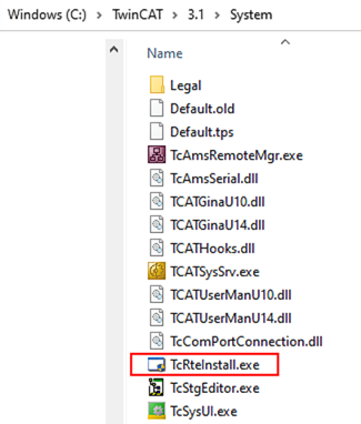
Under the Compatible Devices header, select only the Port that you want your communications on (It will reflect the name you gave it in View Network Connections), and Install and Enable this port.
Do not install the second port, if there are two. Keep the second port on DHCP to allow for backup comms to the IPC if the IP address becomes unavailable.
TwinCAT
In your TwinCAT solution that will be Activated on the IPC.
EIP Master
Add an Ethernet Master to the IO Tree
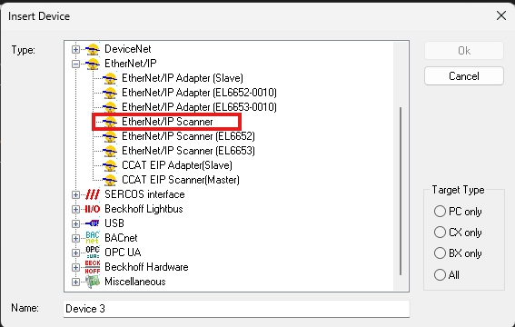
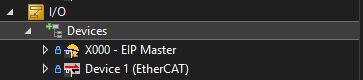
Here, I have renamed the EtherNet/IP Scanner (Master) to match the port that I've set the static IP on.
In the settings for the EIP Master:
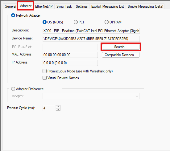
Search for and select the Ethernet Port that you had configured previously (I have already done it here)
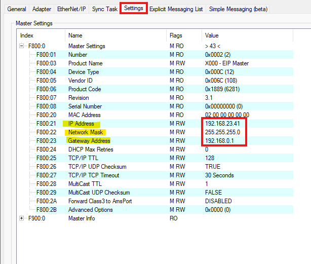
Assign an IP address to the EIP Master
This must be a different IP address than the Ethernet Port on the same subnet. In this example, my IPC EIP port is set to X.X.X.40 and my EIP Master is set to X.X.X.41
Robot EDS
Within the EIP Master, import the Kawasaki EDS File:
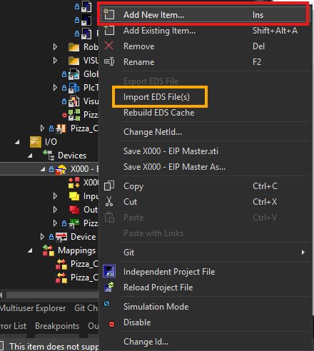
Add new item if you have already imported the EDS file, otherwise import EDS File(s).
Importing and EDS file will require Admin Privileges
The Kawasaki EDS Files can be found at "G:\Robotics\12 - Programming\Beckhoff\Robot EDS Files"
Import both.
When adding, add the Kawasaki_EDS_Slave to the EIP Master.
In the robot EIP properties:
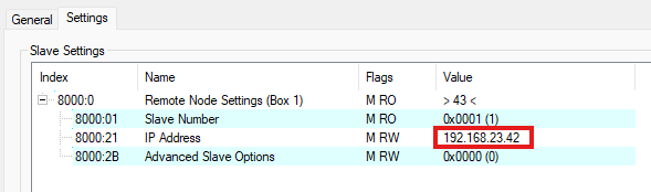
Input the IP of the robot that the IPC will be communicating with.
Robot IO
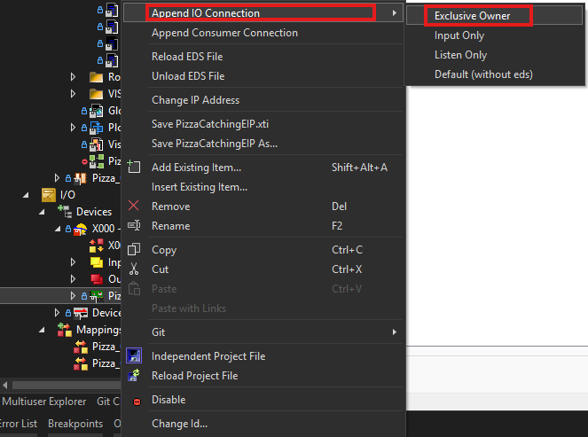
This should add the IO EDS connection with all the IO built in.
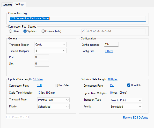
It should have these default settings.